Create Sub Element, with basepoint in another floor.
Sketch Annotation to Topo-surface/Solid
Modify Floors
Define slope
|
|
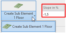
In the Ribbon New Sub Element, the slope must be typed in % , ‰ or e.g. 1/15 or 1:15 (+ Enter). A positive number will create a decreased slope, negative numbers will create an increased slope.
In the settingspanel you can choose if the slope must be typed in % or ‰, (Default is %)
|
Default Floor
|
|
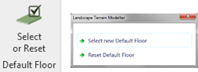
If there is a lot of work in one specific floor, the function Default Floor can save a lot of selecting. If a Default Floor is selected the step ”Select the floor to modify” can be ignored. When working in other floors than the Default Floor, the function must be reset or a new floor must be selected as Default Floor.
|
Create Sub Element
|
|
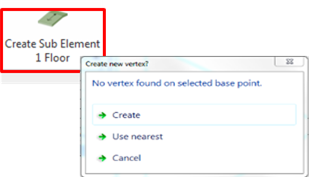
1: Define Slope 2: Select the floor to modify 3: Select the basepoint for the calculation The selected point must be a Sub Element or a point on a line. If the selected point isn’t a Sub Element, the user will be prompted to select if the nearest point is to be used or to create a new Sub Element 4: Select the position for the new Sub Element
|
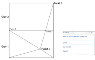
Create Sub Element, with basepoint in another floor
|
Point defined by decrease
|
1: Define Slope
|
|||
|
|
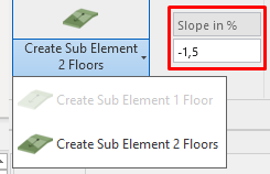
2: Select the floor in which to create the new Sub Element Floor(1) (Default Floor) 3: Select the floor where the basepoint is located Floor(2) 4: Select the basepoint for the calculation The selected point must be a Sub Element or a point on a line. If the selected point isn’t a Sub Element the user will be prompted to select if the nearest point is to be used as basepoint or to create a new Sub element 5: Select the position for the new Sub Element Point(2)
|
|||
|
|
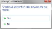
The user will be asked if a new Sub Element is to be created where the line between the basepoint and the placement for the new Sub Element intersect with edges of the two floors Point(3)
Note: If the two floors do not intersect the point will not be created.
|
|||
|
TIPS:
|
If a plane slope is wanted on floor(2) the point(4) It can be set to the same elevation as point(3) by typing the slope 0 and insert a new Sub element in point (4), with point(3) as base point. |
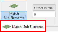
Match Sub Elements
|
|
Two floors sharing the same edges can be modified so the Sub Elements will have the same elevations, or with the same distance in elevations. 1: Type the elevations offset 2: Select the floor with the right elevation 3: Select the floors to be modified
|
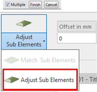
Adjust Sub Elements
|
|
The Sub Elements will be adjusted with the distance typed in the Offset in mm box
1: Type the elevations offset 2: Select the floor(s) in which to adjust the Sub Elements 3: Press Finish (selection) in the upper left corner 4: Draw a window around the Sub elements to Adjust |
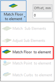
Match Floor to element
|
|
This function will set the elevation on all the endpoints in the floor boundary lines. The elevation will be set to match the selected imported object in the same or nearest point (max. 50 mm). The offset value will be used to calculate the new elevation.
1: Select the “source” element 2: Select the floor(s) in which to add the vertex
Note: Some Blocks/Cells in the DWG/DGN files may cause an incorrect elevation. Therefore they must be removed/exploded before loaded into Revit. It is very important that the dwg only contains the lines/solids, you want to connect floors to otherwise you can get an incorrect elevation. |
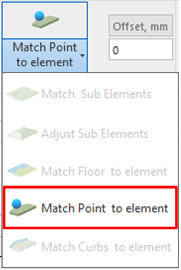
Match Point to element
|
|
This function will be crated a Floor vertex in the selected point with the elevation from the selected imported object in the same or nearest point (max. 50 mm). The offset value will be used to calculate the new elevation.
1: Select the “source” element 2: Select the floor(s) in which to add the vertex 3: Select the points where you want the new vertex
The function will be repeated until “Esc” is pressed.
Note: Some Blocks/Cells in the DWG/DGN files may cause an incorrect elevation. Therefore they must be removed/exploded before loaded into Revit. It is very important that the dwg only contains the lines/solids, you want to connect floors to otherwise you can get an incorrect elevation. |
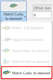
Match curbs to element
|
|
This function will change the elevation of the endpoints of the selected Curbs, or any other family from the category “Structural framing”, to the elevation from the selected imported object in the same or nearest point (max. 50 mm). The offset value will be used to calculate the new elevation.
1: Select the “source” element 2: Select the curb(s) in which to add the vertex 3: Select the points where you want the new vertex
The function will be repeated until “Esc” is pressed.
Note: Some Blocks/Cells in the DWG/DGN files may cause an incorrect elevation. Therefore they must be removed/exploded before loaded into Revit. It is very important that the dwg only contains the lines/solids, you want to connect floors to otherwise you can get an incorrect elevation. |
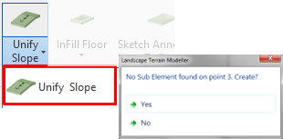
Unify Slope
|
|
1: Select 2 Sub Elements and a point in a line
The slope between the two selected Sub Elements will be registered and the elevation in the 3rd point is calculated. If the 3rd point is a Sub Element the elevation is changed. If the 3rd point isn’t a Sub Element the user will be prompted to Create a new Sub Element. |
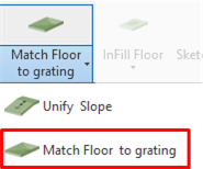
Match Floor to Grating
|
|
Match Floor to Grating will create Sub Elements around a Family to match the Family`s elevation.
1: Make sure the family is in the right elevation 2: Select the Family 3: Select the Floor (If the Family isn’t hosted in the floor)
Note: If a Yes/No Parameter named ”Circular” is present and checked in the Family the function will create 16 Sub Elements around the family. If the parameter isn’t in the family or is unchecked the family is considered a square and 4 Sub Elements will be created around the family. |
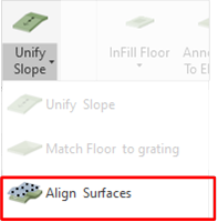
Align surfaces
|
|
Align surfaces will transfer the points from the selected toposurface/Toposolid into the selected floor and create a subelement for each 500 mm around the boundryline of the floor.
|

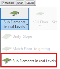
Sub Elements in real Levels
|
|
The Sub Elements in the selected floors will be set to real Levels and the floor will keep the attachment to the Level.
1: Select the floor(s) in which to adjust the Sub Elements 2: Press Finish (selection) in the upper left corner
Notes: If the Sub Elements in the floors have been reset, the offset From Level, must be set to 0 to get the floor in the right position again.
Placing a new Sub Element after using this function: Set the Elevation to 0 and then correct the elevation on the Sub Element. |
|
|
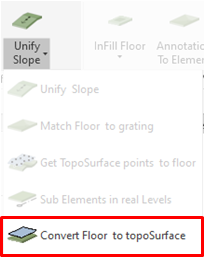
Convert Floor to Toposolid (Revit ver => 2024) Converting the selected floor to a Toposolid. If a Toposolid type with the same name is in the project, it will be used, other ways, a Toposolid type will be created with the same name, layers, materials and surface patterns will be created. Keep or delete the selected floor
Note: Use the convert ‘Create Toposolid types’ in the settings menu to create toposolid types from all the floor types in the project.
|
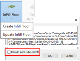
Infill Floor, Create / Update
|
|
InFill Floor create floors inside selected openings. These openings must be vertical openings and drawn independently (two openings drawn in the same sketch will not work).
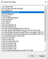
Create. The openings can be selected one by one or with a Window/Crossing selection. If no openings are found in the section, LTM will search for openings in the selected floors. Select a FloorType for the Infill floor.
Select “Include inner SubElements” if the sub-elements from the main floor, placed inside the openings, must be added to the infill floor.
Update. Update the Infill Floor to the geometry of the opening if it is modified.
Tip: Add or remove the inner SubElements, check/uncheck the “Include Inner SubElemnts” on the InFill Floor, before updating. |
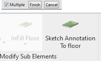
Annotation to Floor
|
|
Annotation on Floor and Toposurfaces, is converting Sketch annotation into vertexes on Floors/Toposolid and/or Toposurfaces. 1: Select the Floors and Toposurfaces to place the new vertexes on. 2: Press Finish (selection) in the upper left corner. 3: Select the Annotations to convert. 4: Press Finish (selection) in the upper left corner.
Notes: If a vertex is outside the floor, the vertex will be ignored. If a vertex is outside a toposurface the toposurface will be extended. |

 Create
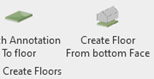
Floor from bottom Face
Create
Floor from bottom Face
|
|
Create Floor from bottom Face, will create a floor on the lowest horizontal bottom face of the selected element.
1: Select the element you want to create the floors 2: Select floortype. |
||||||||||||
Filled Regions
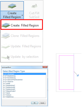
Create Filled Region
|
|
If the floor has different slopes the graphical presentation in Revit isn’t always useful. Create Filled Regions to compensate. 1: Select the floor 2: Select the filled Region Type.
The Filled Region is created with the same extension as the floor. The Floor and the Filled Region will be connected to use the Updated Filled Region. The Surface pattern will be turned off on the selected floors
If the opening touches the bounding line of the floor. It is important that the line of the opening and the bounding line of the floor is aligned.
Note: Filled Regions not created by the function Create Filled Region in this APP, will not response on the function Update Filled Region
|
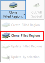
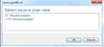
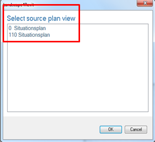
Clone Filled Region
|
|
If one or more Filled Regions are created in one view and the same Filled Region connection to the same floors is wanted in a new view, use the Clone Filled Region Function.
1: Make sure the view to create the Filled Regions is Active 2: Select the view from where the Filled Regions must be cloned.
To keep the connection between the filled Region and the floor to use the Update Filled Region, it is important to use his command instead of copy the Filled Regions |
Update Filled Regions
|
|
If one or more floors are changed to another extension, the Filled Region (created by the create Filled Region function) can by updated by following the floors new extensions. By selecting Update Filled Regions, All Filled Regions in the project with be updated to the floors extension to which they are connected.
Note: By using the Update Filled Regions Function any changes in the filled region, e.g. Rotation or moving the pattern will be reset.
Tip: To find the right place for the pattern in the Filled Regions after the use of Update Filled Regions Draw one or more refplanes where the pattern is located. Use the Align command to align the pattern to the refplanes.
Use Update by Selection to update only the selected Filled Region
|
Calculations
Cut/Fill, SubSoil
|
|
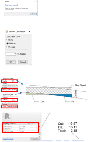
Cut/Fill Subsoil calculates volumes of subsoil to add (fill) or remove (cut).
The first time the Cut/Fill Subsoil is used in a model, LTM will load: - 2 parameters (TopSoil and SubSoil) attached to TopoSurfaces - 3 parameters (SubSoil_Cut, SubSoil_Fill & SubSoil_Total) attached to Property lines - the property line TAG “A-Cut_Fill TAG.rfa”.
You must indicate if the TopoSurface represents the TopSoil or SubSoil before running the calculation.
There are 3 precision levels for the volume calculation: low, medium and high.
The TopSoil must be modelled as an Existing TopoSurface with the parameter “TopSoil” checked.
The SubSoil can be modelled as an Existing TopoSurface with the parameter “SubSoil” checked. Or The SubSoil can be indicated as a distance from the TopSoil when using the function.
The function will calculate the volume (Cut/Fill) between the SubSoil and the bottom of the objects.
The calculation result is stored in the Property lines and can be shown with the PropertyLine TAG “A-Cut_Fill TAG.rfa”. |
Surface soil balance
|
|
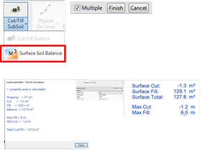
Surface Soil Balance, will calculate the different between the surface on the selected objectes, inside the area of the selected property line.(If the project have more then one property line, you will have to select one to use for the calculation.
Select the eksisting object first then the new onject (Remember to press ‘Finish’ after selection)
Result will be: Cut, fill and total in m³ Max Fill and max cut in meters
The result will be shown in a dialog and stored in the Property, it can be shown with the surfaceCut_Fill TAG, (loaded when using the function)
Note: To select the property, select a property line and press ‘tab’ to select the property Use the Soil balance analyze tool to visualize the data.
|
Line Tools
Objects on Lines
|
|
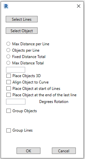
Objects on Lines will place families on the selected lines, the families can be placed in different ways.
1: Select the lines you want the families to be placed along. (Splines will not be included) 2: Select the family.
If the family isn´t placed on start of the lines, you must select a point to mark the start on the Line.
When the lines are selected, the numbers and total length is shown below the select button. When the family is selected the name is shown below the button.
There are 4 ways to place the families. The numbers of objects or distance must be written in the textbox. Max distance per line, will place the objects with a max distance on each line (If the line is longer than the distance).
Objects per Line, will place the written number of objects on each line.
Fixed distance Total, will place the objects with the written distance on the selected lines.
Max distance Total, will place the objects with a max distance on the selected lines.
Place Objects 3D, will adjust the place objects on the Floors or Toposurfaces they are placed on.
Align Object to curve, will rotate the object to match the direction of the line they are places on
Place Object at start of line, will place an object at the start on each line
Place Object at the end of the last line, will place an object at the end of the last line
Degrees Rotation, will rotate the object before placing, e.g. if the object must be placed perpendicular on the lines instead of along the lines.
Group Objects will group all the placed objects, and can be named using the textbox below the checkbox
Group Lines will group all the selected lines, and can be named using the textbox below the checkbox
Some of the options can be combined, e.g. if you want 3 objects on each line and one on the beginning on each line and perhaps an object on the end of the last line.
Additions features: If the selected object is an annotation, used for elevation texts, the elevation will be calculated (using the slope written in the LTM menu).
If the parameter “Length” is attached to Groups, the total length of the selected lines will be written into it. (If the “Group Line” is selected)
If the selected object contains the Parameter “Length” the distance from the start point will be written to it.
|
Convert Splines
|
|
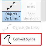
Convert Splins will convert the selected Spline into ARCs, keep or delete the spline.
|
|||||||||||
Annotations
Spot Elevations
|
|
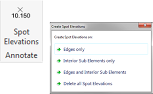
This function will place a Spot Elevation.
1: Select if you want to create or delete spot elevation 2: Select the Floor(s) on which you want Spot elevation 3: Press Finish (selection) in the upper left corner.
Note: The function will use the default Spot Elevation Tag. Insert a Spot elevation manually to change the default. |
Sketch Annotation
The sketch annotations are dynamic, when the annotation are moved or the elevation are changed the slope text will automatic update.
This function will work the first time the project are opened after a sketch annotation are placed in the model.
|
|
The Sketch Annotation is a set of tools to make 2D Sketch Annotation for elevations. These commands require the use of special Families “Sketch_Elevation_Annotation_DK” & “Sketch_Elevation_Annotation_UK” are located at: C:\ProgramData\Autodesk\ ApplicationPlugins \LandscapeTerrainModeller.bundle\ Contents\Resources, or you can use families and location from your company. (Look at “Create Sketch Annotation”).
Note: The new elevations will use the number of digits from the first selected elevation. The functions will run in loop until you press esc. These Functions will NOT be automatically updated if the geometry changes or the annotations are replaced.
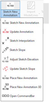
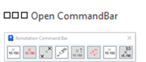
The Annotation Commad Bar, will show the same functions but more accessible than the drowdown. |
|||
|
|
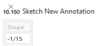
Sketch New Annotation, creates a new Annotation, with a new elevation written. Select an Annotation and pick the position for the new annotation. The new elevation will be calculated using the slope in the LTM Menu.
Note: The slope can be written in %, ‰, 1/15 or 1:15 (% or ‰ are depending of the setting in the model) |
|||
|
|
Update Annotation, will update the elevation on the selected annotation. Select an annotation and select the annotation you want to update The annotation will be updated using the default slope from the LTM menu and the elevation of the 1. selected annotation. |
|||
|
|
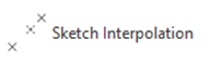
Sketch Interpolation calculate a new elevation between two Annotations. Select First & Second Annotation and the placement for the new annotation, between or continuation of the two annotations. |
|||
|
|
Sketch Slope, add a text between two annotations showing the slope and direction. Select the two annotations and the placement for the slope text.
Note: This function is only available in floorplan oriented in project north, or where true north is aligned with Project north. The function will use the default Text type or the TextType added at “Settings” |
|||
|
|
Adjust Sketch elevation Select the Sketch Annotations you want to adjust, with the value in the LTM “Offset” menu
|
|||
|
|
Update sketch Slope, will update the Sketch slope annotations. The function can be used if some of the elevations have changed, it will update the slope from the new elevation. The texts are updated to the current text style.
Note: This function is only available in floorplan oriented in project north, or where true north is aligned with Project north. |
|||
|
|
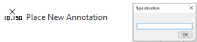
Place New Annotation Place a new Sketch Annotation and type the elevation in the dialog box.
The family Type can be set in the Settings menu.
Note: If the elevation contains “,” or “.” the elevation will be calculated in meter if not it will be calculated in millimetre. |
|||
|
|
Place New Annotation 3D Place a new Sketch Annotation, the elevation will be set from the selected object
1: Select the imported object you want to get the elevation from 2: Select the points to place the Sketch elevation.
The family Type can be set in the Settings menu.
Note: Some Blocks/Cells in the DWG/DGN files may cause an incorrect elevation. Therefore they must be removed/exploded before loaded into Revit. It is very important that the dwg only contains the lines/solids, you want to connect floors to otherwise you can get an incorrect elevation. |
|||
|
|
The commandbar contains the same functions as the Annotation menu, but make it easier to reach the functions.
|

 Slope
text on faces & edges
Slope
text on faces & edges
|
|
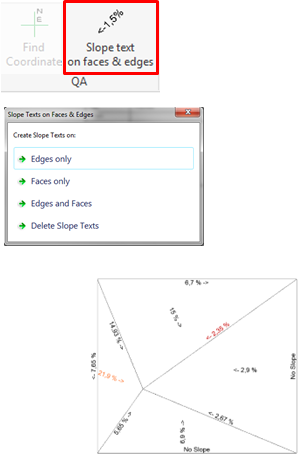
Slope text on faces & edges will place text notes on faces and/or edges on the Floors. 1: Select if you want to create or delete text notes 2: Select the Floor(s) on which you want slope texts 3: Press Finish (selection) in the upper left corner.
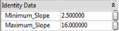
The first time this function is used in the model 2x2 parameters are loaded and attached to floors. Minimum_Slope Minimum_Slope_Type & Maximum_Slope Maximum_Slope_Type
For each Floor Type or Instance you can type in a Minimum and/or a Maximum slope.
If the slope is less than the value in Minimum_Slope(_Type) the texts will be red. If the slope is greater than the value in Maximum_Slope(_Type), the slope texts will be orange. next time the function is used (The colors can be changes in the settings panel)
If there are values in both e.g. Minimum_Slope and Minimum_Slope_Type the value from the instance, Minimum_Slope will be used. When the function is used again the old slope texts will be deleted.
Note: This function is only available in floorplan oriented in project north, or where true north is aligned with Project north.
The Slope Texts are for QA only and they will NOT be automatically updated if the Floor geometry changes. The function will use the default Text type or the TextType add at “Settings” |
Model Lines
|
|
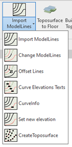
This set of functions gives the possibility to create model lines from imported dwg files, modify those model lines, annotate them and create topo-surface/solids from them.
1. Import Lines 2. Change Style & Elevation 3. Offset Lines 4. Elevation Texts 5. Elevation Info 6. Set New Elevation 7. Create Toposurface |
|||
|
|
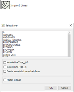
1. Import Lines
Import Lines creates model lines in Revit from a linked .dwg file. The name of the AutoCAD layers in which the elevation lines were will be given to the model lines style in Revit.
Check Include LineType__0.5 to add “_0.5” at the end of the line type’s name. It will only be added to the lines standing at an elevation finishing by 500 (1500, 2500, 10500…).
Check Include LineType__5 to add “_5” at the end of the line type’s name. It will only be added to the lines standing at an elevation finishing by 5000 (5000, 15000, 25000…).
Check Create associated named refplanes to create a reference plane for each model line elevation. The reference planes will be named after the elevations and can be used as work planes (to place modellines, objects, etc. at a specific elevation)
Check Flatten to level if the model lines must be placed on active level, This function is only active in planview.
Note: Do not scale up/down the dwg file before or after linking it in Revit. The units in the dwg file must be defined (meters, millimeters…). |
|||
|
|
2. Change Style & Elevation
Use Change Style & Elevation to copy and paste the properties of a model line. The line style and elevation will be copied.
Click once on the line to copy the properties from. Then select all the lines to paste the properties to. Click finish. |
|||
|
|
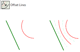
3. Offset Lines
Use Offset Lines to create elevation lines every 500 mm between two other elevation lines.
The chosen lines can either be from the imported model lines or can be drawn manually. There must be a difference of elevation between the two lines or nothing will be created.
Click on Offset Lines, select the first line, then the second at a higher or lower elevation. |
|||
|
|
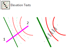
4. Elevation Texts
Use Elevation Texts to tag the elevation of the model lines.
Draw a virtual line (place the start point, then the end) to define which elevation will be tagged and where. A text will be placed at every intersection between the “virtual line” and the elevation lines.
|
|||
|
|
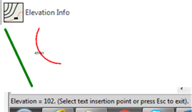
5. Elevation Info
Use Elevation Info to know and eventually tag the elevation of a model line.
Click on Elevation Info then click on a line: the elevation will be written on the bottom left corner of Revit. Click again to place an elevation tag or press Esc to exit. |
|||
|
|
6. Set New Elevation Use Set New Elevation to change the elevation of the selected model Lines Write the new elevation in the dialog box and select the ModelLines and press Finish, in the upper left cornor.
|
|||
|
|
7. Create Topo-surface/Solid
Use Create Topo-surface/Solid to create a topo-surface/Solid from the selected model lines.
Click on Create Toposurface then select the model lines and click Finish on the top left corner of Revit. |
TopoSurfaces
TopoSurface to Floor
|
|
This function will convert a Topography into a Floor.
1: Select a Topography 2: Select a Floor Type from the list
Note: The Sub Region must be inside the Topography. Boundary loop inside another loop, can make the Floor unstable, use opening instead. Building Pads are ignored by this function |
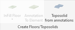
Sketch Annotation to Topo-surface/Solid
|
|
Annotations to Topo-surface/solid (Revit ver => 2024) The selected Sketch annotations will create a topo-surface/solid, if no annotations are selected all the annotations in the active view will be used. |
Buildings on Toposurface
|
|
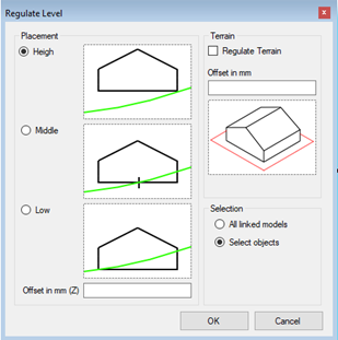
Buildings on TopoSurface adjust the Z value on the selected objects to match the Toposurface. Select the placement and write an Offset (Z) if needed.
If you want to regulate the terrain around the building, check the Regulate Terrain, checkbox. Write the wanted offset around the building.
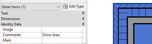
Note: If it is a linked model containing a Filled Region, with the value Gross Area, in the property Comments, LTM will use the boundary lines from this Filled Region as basis to the terrain regulation otherwise the bounding box will be used. |
Find Coordinate
|
|
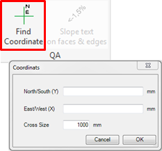
This function will create a cross on a specific coordinate
1: Type in coordinate values for both directions 2: Change the size of the cross, if necessary
|
Import/Export
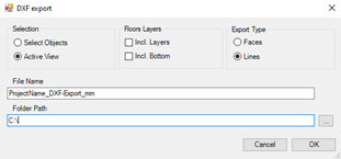
DXF export
|
|
This function will create a DXF file, with all the edges in the active view as 3D lines e.g. for importing in Microstation OpenRoad, or Mike Urban. |
|||
|
|
You have several options for the export: Export all objects in the active view, or selected objects. Export Type: Select Lines or faces.
Floor Layers: (Only if Lines are selected as export type). “Incl. Bottom” The export will contain lines for the top surface and the bottom layers. By “Incl. Layers”, the export will contain lines for each layer in the floors. If nothing is selected, only the top layer will be exported. |
|||
|
|
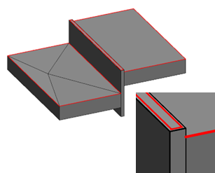
When 3D lines are imported in software to create faces, they will normally not allow points or lines in the same position but with different height (Z value) If floors around a retaining wall are exported this situation will appear, therefore if walls are exported, only the top face will be exported and the upper face will be offset to avoid this problem.
In the same way, if the model will be used in a calculation in another software, that eg. need the groundfloor level to be models as well, it can be done with Floors. If the FloorType have a checked Yes/No parameter called “FaceOffset” (the Parameter name can be chaged in the settings menu) and the floor are horizontal without any vertexes, the boundary lines will be exported with the same offset as the wall top face.
If floors are modelled close to imported objects it is very important to keep a distance of eg. 10 mm to the object to avoid the “Points in same point but different elevation” |
|||
|
|
Naming of exported layers. All the layers in the DXF file will be named according to the object they are created from. Default export settings: Line/Faces created from Floors will get the Family Name, Faces created from TopoSurfaceses will be placed on the Layer “Surface”
If the Parameter DXF_Export_As is attached to the object (as instance) and the value is not empty, the value will be used as layer name in the DXF export.
If the Parameter DXF_Export_As_Type is attached to the object Type (Floors and Walls only) and the value is not empty, this value will be used as layer name in the DXF export. The DXF_Export_As_Type value will only be used if the DXF_Export_As value is empty.
If the floor layers are exported, they will be named with the “floor name” ”Material of the Layer” the bottom of the floor will be named: “floor name” ”Bottom” All the interior break lines will be named as written above with “_int” added in the end of the name.
Note: In this Export manual the parameter names DXF_Export_As and DXF_Export_As_Type are used, they can be changed in the settings menu.
DXF has a max of 30 characters in the file name that means that additional letters will be ignored. A DXF Layer can’t begin with a number, if the Layer Name does that, there will be added a “_” in the beginning to avoid that problem. In the same way special characters will be replaced with “_” in the layer name. |
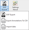
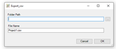
Export Annotations To CSV
|
|
This function will export the values and the position of Sketch Annotations into a csv file.
1: Select the Sketch annotation you want to export, if nothing is selected, all the annotations in the active view will be exported. 2: Select path and name for the export csv file.
|
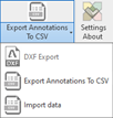
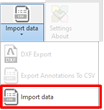
Import data
|
|
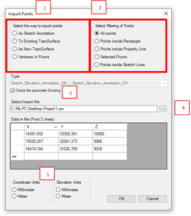
This function will import “points data” from different kind of data formats in different ways into Revit.
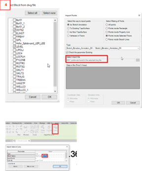
1: Select the way to import points (Different ways to use the imported data) 1.1 As sketch Annotation, (Floorplan only) will place a Sketch annotation from each point in the file, in the active view. Select the Family Type to place. 1.2 To Existing Toposurface, you will be asked to select the toposurface you want to add point to. 1.3 As New Toposurface, this will create a new toposurface. 1.4 Vertexes in Floors, you will be asked to select the floor you want to add point to. 2: Select Filtering of Points (different ways of sorting the points before importing) 2.1 All points in the File 2.2 Points inside a rectangle. If you only want points inside a rectangle (Select the two diagonal corners with “left click” on the mouse). 2.3 Points inside Property Line. You will be asked to select the Property Line. 2.4 Selected Floors only points inside the selected floor will be imported. Points inside Sketch Lines. (Floorplan only) 2.5 Draw lines and end with “ESC” (Floorplan only). 3: Check the parameter indicating if it is an existing elevation point. 4: Select the import file. (on the bottom to the right) If an imported dwg file is selected before using the import function, all the block names in the file are listed. Select the name(s) of the elevation points and all their inserts points are ready to import: The total numbers of the selection are written instead of the import file.
Notes: In some cases floors and property lines can’t be used to filter the points. In that case the elements boundary will be used. Use the Revit function “Import instance Query” to find the block name of the elevation points.
5: Select units. Select units for coordinates and elevation (The first 3 lines in the file will be shown) Units are disabled if you are using points from a dwg file |
|||||||||||||||||||||||
Analyze
|
|
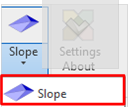
Analyze, Slope Slope will color all the upper faces with a slope on the selected objects.
Note:
If any objects are selected, the objects are used for the analysis. The colors for “Slope Small” and “Slope Large” are used, they can be set in the settings panel. |
|||
|
|
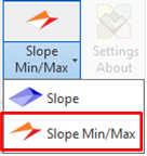
Analyze, Slope Min/Max Slope will color all the upper faces that don’t match the conditions in the parameters “Minimum_Slope” and “Maximum_Slope” on the selected objects.
Note: If any objects are selected, the objects are used for the analysis. The colors for “Slope Min” and “Slope Max” are used, they can be set in the settings panel.
|
|||
|
|
Analyze, Soil Balance Soil Balance will use the data created with the ‘Surface soil balance’ function.
Note: The colors for “Surface Fill” and “Surface cut” are used, they can be set in the settings panel.
|

Settings
|
|
Settings: At the “About” dialog select “Settings”
(Revit => 2024) Create Toposolid Types will create from the floor types in the project Toposolid types will be created with the same name, layers, materials and surface patterns as the floors will be create. |
|
|
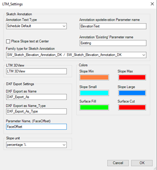
Annotation Text Type: Set the text Type to use at the functions: Slope Text on Faces and Edges and Sketch annotation.
Annotation spotelevation Parameter name, is the name of the parameter where the Elevation is written, if the field is empty, the name “ElevationText“ is used.
Annotation ‘Existing’ Parameter name, is the name of the parameter used for marking if the elevation is existing.
If Place Slope Text at Center is checked, the slope text will be placed automatically right between the two elevation points. If it is uncheked you must select a placement for the text.
Family type for sketch Annotation, is the family type used everywhere the Sketch annotations placed.
LTM 3Dview Some functions need a 3D view to run, in the background. To reduce loading time a view with this name will be used to those functions. It it is poisibel to make special settings, (e.g. show dwg models, hide links, specisl categories etc.
DXF Export as Name, the name of the (text)parameter if you want another layer name on the floor/Wall than the type Name in the DXF export function.
DXF Export as Name_Type the name of the (text)parameter if you want another layer name on the floor/Wall TYPE than the type Name in the DXF export function.
Parameter Name (Offset) the Name of the (Yes/No) Parameter to indicate if the face must be offset in the DXF export.
Colors Press the square to set the colors for analyzes. Slope Min and Slope Max, is for the analysis Slope Min/Max that uses the parameters Minimum_Slope and Minimum_Slope_Type on the floors.
Slope Small & Slope Large is for slope analyze Cut & Fill is for the Surface volume calculation
Surface Cut,- Fill is for cut/Fill surface analyze
Slope units Slope units control the unit typed in the ‘slope box’ in the ribbon panel AND controls the units on the Annotation slope texts.
|
Create Sketch Annotation
|
|
Some of the functions are using a 2D Annotation for Spot Elevations. It is possible to make your own families.
Sketch Annotation must have a instance parameter called “ElevationText” or a parameter defined in the settings menu of the ParameterType “Text” where the elevation must be written. If the Parameter is called another name, it must be written in the Settings Textbox, “Annotation spotelevation Parameter name”
The functions will do the calculation of elevations based on the insert point in the family.
If the text contains a comma (“,”) or a fullstop (“.”), the elevation will be calculated in meters, if not the elevation is in millimeter. All characters but numbers, “,” “.” & “-“ (In case of negative elevations) will be ignored of this function, eg. if you want to set prefix with letters or () it is OK. |
Create Crubs Family
|
|
The function “Match Crubs to element” requires the crubs to be created in the category “Structual Framing”, because those families have the availability to use 3D snapping when the are placed and they can be adjusted differently in each end. |
Other:
The new TopoSolid category will replace the toposurface in Revit 2024 and newer,
All the functions in LTM using Floors will work on floors AND Toposolids from version 2024.
Funktions only available in Revit 2024 are marked: (Revit ver => 2024)
Known issues:
- The functions will only work on Floors and or Toposolids from version 2024
- Floors and openings must only be created in one closed loop.
- Floors with complex geometric forms can cause LTM not to compute.
- Some Topographies with complex forms can make it impossible to create the floor or edit the floor boundaries. Alternatively, these can be divided using Split Surface to avoid very large complex floors.
- Some Openings with complex forms or to many edges, can make it impossible to create InFill floors.
- The DWG file used in the function Import Model must NOT be scaled inside Revit
- Some Blocks/Cells in the DWG/DGN files can give a wrong elevation, therefore they must be removed/exploded before loaded into Revit.
- It is very important that the dwg only contains the lines/solids, you want to connect floors to otherwise you can get an incorrect elevation.
Privacy policy:
- LTM does not collect any data about the user or the use of LTM - Landscape Terrain Modeller